NavList:
A Community Devoted to the Preservation and Practice of Celestial Navigation and Other Methods of Traditional Wayfinding

Making your own spirit level vials-without attached pictures
From: Randall Morrow
Date: 2012 Jan 5, 08:32 -0800
Second posting without attached pictures:
Making a 10 second spirit level vial for a mirror artificial horizon.
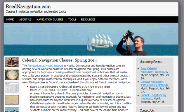
To use a mirror as an artificial horizon it must be carefully leveled out. Machinist levels are available to 20 seconds of arc but they are expensive, starting at around $70.00 on e-bay and rather large for the purpose. You can buy a mirror a.h. with level vials already included, from Freiberger, but it will set you back around $900.00. The cheaper route is to make your own spirit levels. With a home made level vial sensitive to about 10 seconds of arc, it is possible to get very respectable results using a mirror artificial horizon. (Routinely, intercepts from 0 to 1.5 miles using a Davis Mark 15 sextant.) I have made more than a thousand observations this year using a mirror a.h. and would recommend them to anyone for accuracy, ease of use and speed of set-up. What follows is a ‘how-to’ on building a jig to grind glass level vials. The design is a simplified version of a design by Bill Morris and he generously provided a very detailed article he had written on the subject some years ago. (Article by B. Morris in another posting) I realize there is too much detail for most Nav-list members but I wanted anyone to be able to follow it. (Photos attached below)
A very sensitive spirit level vial is just a glass tube ground on the inside, into a minutely tapered barrel shape. This grinding is done by spinning the tube on a slightly curved round steel bar that has been smeared with a grinding paste. The trick is getting the correct curve on the bar and holding that very small curve as you spin the tube by hand. Mr. Morris’s article shows such a jig made by a skilled machinist with access to sophisticated tools.
The jig is made from a section of 1 x 1 mild steel square tube cut to about 18 inches length. Centered on the bar, drill a pair of 5/16 in. holes with centers exactly 340mm apart. This distance is important as it is part of the math for getting the correct arc on the grinding bar. Drill another pair of holes outside these, spaced about two inches outside the first holes. This distance is not critical. The holes can be done by “eye” with a hand drill since it will not matter if they are tilted a little. Four, five inch long, 5/16 eye bolts are inserted through these holes, with nuts/washers above and below the tube. A pair of bar clamps is used as a base to hold the jig as the vial is spun. A round 3/8 inch diameter, 18 inch long steel rod is inserted through the four eye bolts with the glass tube slid on in the middle. You must have the glass tube slid over the bar before set up. The outer pair of eye bolts is then tightened; pulling the bar ends downward forcing the bar to bend. Bend the bar in this way until it is displaced from straight by only 0.28 mm, checking with a feeler gauge/spacer combination. (For a 10 second vial) This is not much of a bend, roughly 10 times the thickness of a human hair. It is difficult to verify this bend with the feeler gauge. A large bolt can be used as a spacer, in conjunction with the feeler gauge, setting the ends of the bar at the height of the bolt, moving the bolt to the center, and bending until the feeler gauge just fits between the bolt and . When the correct bend is achieved, tighten both the top and bottom bolts to lock the curve of the bar in place. During grinding you may stop and verify the correct bend by sliding the tube aside and putting the bolt and feeler gauge in the center. Having too much bend is the greater risk so under-bend rather than over-bend. More bend means decreased sensitivity and you can always grind more after testing.
To start the grinding, the curved bar is smeared with a coarse automobile valve grinding paste and the tube spun back and forth with a wooden paddle to shape the inside of the tube. The grinding paste is that used to polish engine valves and both a coarse and fine grade is needed. They are available in a two-pack from Amazon for $12.11 as “Powerbuilt Valve Lapping Compound. To spin the tube by hand, the wooden paddles are covered with a thin sheet of rubber. To make the paddles for spinning the tube use ¼ inch thick wood and cut this into one 1.5 width and another 6 inch width. The narrow paddle was just a rectangle and the wider was cut with a handle for easier grip. In a test run it took 15-20 minutes of doing push-pull cycles with the small paddle to get the ground area out to the edges of the vial. (In his article Mr. Morris recommends a preliminary grind on a straight bar to ensure a consistent internal diameter.) Initially use a 1 inch wide paddle in the center of the vial, then as the ground ‘frosted” area reaches the edges of the vial switch a paddle that is the width of the vial. Only use enough pressure to get the tube to spin because excessive pressure will tend to flatten out the desired curve of the bar. After the desired internal shaped is achieved, the vial and bar are cleaned of coarse paste and then given a final polish with a fine grind/polishing paste to finish the inside of the tube. Clean the tube thoroughly as any residue will be floating in your vial afterwards. It is possible to change from coarse to fine paste without removing the tube form the jig. Slide the vial to one side and wipe the bar clean. You may then smear on the fine paste and resume grinding. After the first run of grinding you should test the curvature by filling and using temporary rubber caps.
The glass tubing for the vial was purchased from an on-line glass-blowers supply shop for less than $5.00 in a five foot length. This length will yield about nine 12.5 mm long vials. Shipping was about $11.00. The glass company did ask if it was OK to cut the tubing into 3 sections to decrease shipping charges. Tubing wall thickness of 2.5 mm wall was used, so enough material is available in the wall to keep it from losing strength as glass is ground away from the inside. (In retrospect I could have used 1.8 to 2.0 mm wall thickness.) The glass tube can be cut to length with a Dremel-type diamond cut-off wheel. To avoid the need for machining the end caps, a glass tube of 16 mm OD was chosen that would allow use of stock brass pipe fittings for the caps.
Caps are made from brass ‘compression fittings’ that are threaded, have six flats and cost less than $3.00 each. The ID of these caps is 16.01 mm or so. It may be necessary to touch the inside of the caps with a small sanding drum if the fit is too tight. Before gluing the caps in place a 6/32 inch hole is drilled and tapped into one of them then plugged by a screw. This is allows the vial to be filled/refilled as needed. A tiny strip of plumbers tape is wrapped around the machine screw stopper to assure sealing. Measure the thickness each of the six flats on both caps and try to match up a pair of sides of equal thickness, to be on the lower side of the vial as it is glued in place. If there are small differences, remember that the level scale is applied and adjusted after construction and can make up for slight discrepancies in the shape/thickness of the end caps. The caps are glued in place using an epoxy such as Araldite or other solvent resistant two-part clear epoxy, available for around $5.00. The curing time can be up to 12 hours. The end cap threads fill in with epoxy giving extra surface area for a proper seal. Roughening the gluing surface of the glass tube ends before gluing may also be a good idea.
The tubes are filled with denatured alcohol, leaving enough space for an air bubble 3-4 cm long. A drop of food coloring can be added for tint to make the bubble more visible. If fluid leaks over time it can be refilled in the same way.
To test the accuracy of the level during and after completing grinding, first clean the vial, fill appropriately and cap with rubber stoppers. Attach the capped vial to a thick straight edge and shim up one side with a feeler gauge of ‘T’ mm to form a triangle underneath. It is advised that you “ concentrate on getting symmetrical bending and then, when you have even grinding all around, check the vial using feeler blades, a straight edge and simple trigonometry. Some simple math/trig is used, T/L = tan A, so A = inverse tan A. If the tested sensitivity is correct you are ready to polish and assemble with brass caps. If not, you may do additional lapping as needed. The distance in mm the bubble moves when you insert the feeler, is divided by 2.5 to give the number of divisions of movement and divide the angle A by that figure to give the sensitivity of the level per division. But you will not be able to measure these distances without feeler gauges and they turn out to be only a very rough guide. You measure the distance the bubble moves when you insert the feeler, divide by 2.5 to give the number of divisions movement and divide the angle A by that figure to give the sensitivity of the level per division. (see 1st paragraph, p 41).” (Italics by B. Morris)
After testing and more grinding if needed, clean the vial very thoroughly, glue on the brass caps and fill with denatured alcohol. You must attach the scale to the vial and detailed instructions and here are detailed instructions:
“1) Print out the scale and get it copied to an overhead projection film. Cut it to a strip 100 long and 40 mm wide, which is about 7 mm less than the circumference of the tube.
2) Place the level on a flat, smooth and approximately level surface. If your hospital instrument maker has a surface plate, that would be ideal, or the top of a milling machine table.
3) On this surface will be some line which is level, so you swing the level around until the bubble is about central and make an ink mark at each end.
4) Lay a heavy straight edge along side it to mark the position accurately and reverse the level end for end. IF the bubble stays between the marks, you’ve been lucky. GOTO 6) ELSE...
5) If not, mark the ends again and swing the level to split the difference. GOTO 4)
6) Lay the strip on top of the level so the bubble is centrally between the marks and mark the position of the strip at each end on the tube. Clean other marks off the tube.
7) Carefully wrap the strip around the tube, printed side down, and secure it with a long strip of sellotape. Check that the ends are aligned with the marks ELSE remove it and GO TO 5)
8) To check, swing the level until the bubble is central on the scale, Lay the straight edge alongside and reverse end for end. The bubble should stay central.” (Italics by B. Morris)
With his kind permission, I will be posting Mr. Morris's detailed article soon. My thanks to him for his generous assistance.
Randy
Randall F Morrow PT
Ergonomics Safety Consultant
Chronic Pain Program
Kaiser Permanente - Kern County - Bakersfield
NOTICE TO RECIPIENT: If you are not the intended recipient of this e-mail, you are prohibited from sharing, copying, or otherwise using or disclosing its contents. If you have received this e-mail in error, please notify the sender immediately by reply e-mail and permanently delete this e-mail and any attachments without reading, forwarding or saving them. Thank you.


From: Randall Morrow
Date: 2012 Jan 5, 08:32 -0800
Second posting without attached pictures:
Making a 10 second spirit level vial for a mirror artificial horizon.
To use a mirror as an artificial horizon it must be carefully leveled out. Machinist levels are available to 20 seconds of arc but they are expensive, starting at around $70.00 on e-bay and rather large for the purpose. You can buy a mirror a.h. with level vials already included, from Freiberger, but it will set you back around $900.00. The cheaper route is to make your own spirit levels. With a home made level vial sensitive to about 10 seconds of arc, it is possible to get very respectable results using a mirror artificial horizon. (Routinely, intercepts from 0 to 1.5 miles using a Davis Mark 15 sextant.) I have made more than a thousand observations this year using a mirror a.h. and would recommend them to anyone for accuracy, ease of use and speed of set-up. What follows is a ‘how-to’ on building a jig to grind glass level vials. The design is a simplified version of a design by Bill Morris and he generously provided a very detailed article he had written on the subject some years ago. (Article by B. Morris in another posting) I realize there is too much detail for most Nav-list members but I wanted anyone to be able to follow it. (Photos attached below)
A very sensitive spirit level vial is just a glass tube ground on the inside, into a minutely tapered barrel shape. This grinding is done by spinning the tube on a slightly curved round steel bar that has been smeared with a grinding paste. The trick is getting the correct curve on the bar and holding that very small curve as you spin the tube by hand. Mr. Morris’s article shows such a jig made by a skilled machinist with access to sophisticated tools.
The jig is made from a section of 1 x 1 mild steel square tube cut to about 18 inches length. Centered on the bar, drill a pair of 5/16 in. holes with centers exactly 340mm apart. This distance is important as it is part of the math for getting the correct arc on the grinding bar. Drill another pair of holes outside these, spaced about two inches outside the first holes. This distance is not critical. The holes can be done by “eye” with a hand drill since it will not matter if they are tilted a little. Four, five inch long, 5/16 eye bolts are inserted through these holes, with nuts/washers above and below the tube. A pair of bar clamps is used as a base to hold the jig as the vial is spun. A round 3/8 inch diameter, 18 inch long steel rod is inserted through the four eye bolts with the glass tube slid on in the middle. You must have the glass tube slid over the bar before set up. The outer pair of eye bolts is then tightened; pulling the bar ends downward forcing the bar to bend. Bend the bar in this way until it is displaced from straight by only 0.28 mm, checking with a feeler gauge/spacer combination. (For a 10 second vial) This is not much of a bend, roughly 10 times the thickness of a human hair. It is difficult to verify this bend with the feeler gauge. A large bolt can be used as a spacer, in conjunction with the feeler gauge, setting the ends of the bar at the height of the bolt, moving the bolt to the center, and bending until the feeler gauge just fits between the bolt and . When the correct bend is achieved, tighten both the top and bottom bolts to lock the curve of the bar in place. During grinding you may stop and verify the correct bend by sliding the tube aside and putting the bolt and feeler gauge in the center. Having too much bend is the greater risk so under-bend rather than over-bend. More bend means decreased sensitivity and you can always grind more after testing.
To start the grinding, the curved bar is smeared with a coarse automobile valve grinding paste and the tube spun back and forth with a wooden paddle to shape the inside of the tube. The grinding paste is that used to polish engine valves and both a coarse and fine grade is needed. They are available in a two-pack from Amazon for $12.11 as “Powerbuilt Valve Lapping Compound. To spin the tube by hand, the wooden paddles are covered with a thin sheet of rubber. To make the paddles for spinning the tube use ¼ inch thick wood and cut this into one 1.5 width and another 6 inch width. The narrow paddle was just a rectangle and the wider was cut with a handle for easier grip. In a test run it took 15-20 minutes of doing push-pull cycles with the small paddle to get the ground area out to the edges of the vial. (In his article Mr. Morris recommends a preliminary grind on a straight bar to ensure a consistent internal diameter.) Initially use a 1 inch wide paddle in the center of the vial, then as the ground ‘frosted” area reaches the edges of the vial switch a paddle that is the width of the vial. Only use enough pressure to get the tube to spin because excessive pressure will tend to flatten out the desired curve of the bar. After the desired internal shaped is achieved, the vial and bar are cleaned of coarse paste and then given a final polish with a fine grind/polishing paste to finish the inside of the tube. Clean the tube thoroughly as any residue will be floating in your vial afterwards. It is possible to change from coarse to fine paste without removing the tube form the jig. Slide the vial to one side and wipe the bar clean. You may then smear on the fine paste and resume grinding. After the first run of grinding you should test the curvature by filling and using temporary rubber caps.
The glass tubing for the vial was purchased from an on-line glass-blowers supply shop for less than $5.00 in a five foot length. This length will yield about nine 12.5 mm long vials. Shipping was about $11.00. The glass company did ask if it was OK to cut the tubing into 3 sections to decrease shipping charges. Tubing wall thickness of 2.5 mm wall was used, so enough material is available in the wall to keep it from losing strength as glass is ground away from the inside. (In retrospect I could have used 1.8 to 2.0 mm wall thickness.) The glass tube can be cut to length with a Dremel-type diamond cut-off wheel. To avoid the need for machining the end caps, a glass tube of 16 mm OD was chosen that would allow use of stock brass pipe fittings for the caps.
Caps are made from brass ‘compression fittings’ that are threaded, have six flats and cost less than $3.00 each. The ID of these caps is 16.01 mm or so. It may be necessary to touch the inside of the caps with a small sanding drum if the fit is too tight. Before gluing the caps in place a 6/32 inch hole is drilled and tapped into one of them then plugged by a screw. This is allows the vial to be filled/refilled as needed. A tiny strip of plumbers tape is wrapped around the machine screw stopper to assure sealing. Measure the thickness each of the six flats on both caps and try to match up a pair of sides of equal thickness, to be on the lower side of the vial as it is glued in place. If there are small differences, remember that the level scale is applied and adjusted after construction and can make up for slight discrepancies in the shape/thickness of the end caps. The caps are glued in place using an epoxy such as Araldite or other solvent resistant two-part clear epoxy, available for around $5.00. The curing time can be up to 12 hours. The end cap threads fill in with epoxy giving extra surface area for a proper seal. Roughening the gluing surface of the glass tube ends before gluing may also be a good idea.
The tubes are filled with denatured alcohol, leaving enough space for an air bubble 3-4 cm long. A drop of food coloring can be added for tint to make the bubble more visible. If fluid leaks over time it can be refilled in the same way.
To test the accuracy of the level during and after completing grinding, first clean the vial, fill appropriately and cap with rubber stoppers. Attach the capped vial to a thick straight edge and shim up one side with a feeler gauge of ‘T’ mm to form a triangle underneath. It is advised that you “ concentrate on getting symmetrical bending and then, when you have even grinding all around, check the vial using feeler blades, a straight edge and simple trigonometry. Some simple math/trig is used, T/L = tan A, so A = inverse tan A. If the tested sensitivity is correct you are ready to polish and assemble with brass caps. If not, you may do additional lapping as needed. The distance in mm the bubble moves when you insert the feeler, is divided by 2.5 to give the number of divisions of movement and divide the angle A by that figure to give the sensitivity of the level per division. But you will not be able to measure these distances without feeler gauges and they turn out to be only a very rough guide. You measure the distance the bubble moves when you insert the feeler, divide by 2.5 to give the number of divisions movement and divide the angle A by that figure to give the sensitivity of the level per division. (see 1st paragraph, p 41).” (Italics by B. Morris)
After testing and more grinding if needed, clean the vial very thoroughly, glue on the brass caps and fill with denatured alcohol. You must attach the scale to the vial and detailed instructions and here are detailed instructions:
“1) Print out the scale and get it copied to an overhead projection film. Cut it to a strip 100 long and 40 mm wide, which is about 7 mm less than the circumference of the tube.
2) Place the level on a flat, smooth and approximately level surface. If your hospital instrument maker has a surface plate, that would be ideal, or the top of a milling machine table.
3) On this surface will be some line which is level, so you swing the level around until the bubble is about central and make an ink mark at each end.
4) Lay a heavy straight edge along side it to mark the position accurately and reverse the level end for end. IF the bubble stays between the marks, you’ve been lucky. GOTO 6) ELSE...
5) If not, mark the ends again and swing the level to split the difference. GOTO 4)
6) Lay the strip on top of the level so the bubble is centrally between the marks and mark the position of the strip at each end on the tube. Clean other marks off the tube.
7) Carefully wrap the strip around the tube, printed side down, and secure it with a long strip of sellotape. Check that the ends are aligned with the marks ELSE remove it and GO TO 5)
8) To check, swing the level until the bubble is central on the scale, Lay the straight edge alongside and reverse end for end. The bubble should stay central.” (Italics by B. Morris)
With his kind permission, I will be posting Mr. Morris's detailed article soon. My thanks to him for his generous assistance.
Randy
Randall F Morrow PT
Ergonomics Safety Consultant
Chronic Pain Program
Kaiser Permanente - Kern County - Bakersfield
NOTICE TO RECIPIENT: If you are not the intended recipient of this e-mail, you are prohibited from sharing, copying, or otherwise using or disclosing its contents. If you have received this e-mail in error, please notify the sender immediately by reply e-mail and permanently delete this e-mail and any attachments without reading, forwarding or saving them. Thank you.