NavList:
A Community Devoted to the Preservation and Practice of Celestial Navigation and Other Methods of Traditional Wayfinding
From: Robin Stuart
Date: 2013 Feb 9, 14:07 -0800
A simple plausible locking mechanism for the HR1 was described by Douglas Denny on this list http://fer3.com/arc/m2.aspx/wrapped-Bygrave-DouglasDenny-jan-2010-g11537
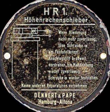
I would like to understand how this mechanism relates to the instructions on the HR1 for adjusting the lock and in particular the function of the stop pin located under the locking knob. I attach a picture of the instructions which includes a diagram. References below to stop pin “b” and screw “a” relate to the this diagram. My attempt at a translation from the German is as follows:
If clamping is unreliable, loosen screw “a” on the locking knob. Turn the stop pin “b” until clamping is again reliable. Tighten screw “a”. Do not undertake any other repairs.
Ronald van Riet’s “Position Line Slide Rules: Bygrave and Höhenrechenscheiber” states that the tube is locked by turning the knob counterclockwise and unlocked by turning clockwise against a stop. For a right-handed screw turning counterclockwise would move the screw out of the tube and would be consistent with Douglas’ design, (“a threaded disk on the top which when turned pulls the rod up”). By impinging on the endcap of the (co)tangent tube, the stop pin “b” then presumably just limits how many turns the locking knob can be away from its locked position. As parts wear it would be expected that the user would need to turn the locking knob further in order to lock the tube but the mechanism would still function. As a convenience one would then lengthen stop pin “b” but this is not required for locking to occur. Is this description consistent with what our fortunate HR1 owners observe in practice?
Is stop pin “b” threaded into the body of the locking knob or does it just slide in and out of a smooth hole secured in position by the screw “a”?
Thanks in advance for any light you can shed,
Robin Stuart
----------------------------------------------------------------
NavList message boards and member settings: www.fer3.com/NavList
Members may optionally receive posts by email.
To cancel email delivery, send a message to NoMail[at]fer3.com
----------------------------------------------------------------
